
 Nederlands
 Français
 Deutsch
 Svenska
 Español
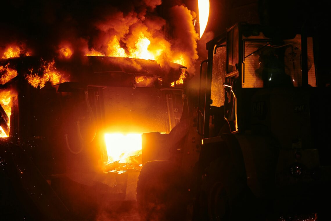
December 2005. Hertfordshire, UK. The Buncefield fuel terminal explodes. Over 40 injured. Luckily, no fatalities. Properties around the depot damaged. A large area evacuated. The fire burned for several days.
It is the largest peacetime fire in modern European history. The investigation that follows rewrites the European standard for foam-water suppression on fuel storage sites. What it concludes is straightforward: the foam blanket either forms in time, or it does not. There is no second version of the fire to try again on.
What determines whether the blanket forms is the foam-to-water ratio at the proportioner. What determines whether that ratio holds is something most engineers do not think about until it is too late: the water flow rate at the proportioner inlet.
This is an article about the unsung component that holds that flow rate where the proportioner needs it. It is also an article about the engineering reason most foam-water systems quietly underperform somewhere between the design event and the inspection records — and what changes when the variable that defeats the proportioner is removed upstream of it.
The mechanism — why ratio drifts before the fire ever reaches it
A foam-water suppression system blends foam concentrate with water at a fixed proportion. Common ratios are 1%, 3%, and 6% concentrate-to-water by volume. The blend happens at a proportioner — typically a balanced-pressure, in-line balanced-pressure, or around-the-pump bladder-tank device — installed between the fire-water main and the discharge devices (sprinklers, monitors, hose lines).
The proportioner’s job is to balance concentrate pressure against water pressure. It does this well within a defined operating envelope. What the proportioner cannot do is compensate for water flow rate drift. Feed it the design water flow and it doses concentrate at the design ratio. Feed it half that flow and the resulting ratio is set by the geometry of the metering port, not by the standard the system is supposed to meet.
NFPA 11 (Standard for Low-, Medium-, and High-Expansion Foam) specifies foam concentration accuracy of −0/+30% of design — concentrate must never fall below the design ratio. EN 13565-2 imposes equivalent constraints in European jurisdictions. Both standards presume that the proportioner is operating within its design flow envelope. Neither standard tells the system designer how to ensure that envelope is maintained.
The cause-and-effect chain is short:
System pressure varies → water flow at the proportioner inlet shifts → metered concentrate ratio drifts → foam concentration falls outside specification → the suppression blanket forms thinner, slower, or with the wrong expansion ratio.
This chain runs in fewer than ninety seconds — typically the time between fire detection and full-system activation. Within that window, the foam blanket either establishes or it does not. There is no second chance to recalibrate.
Why pressure does not stay where the design assumes
A fire pump has a pump curve. Discharge pressure is a function of flow demand, not a constant. As demand grows — additional sprinkler heads opening, additional monitors activated, hose lines deployed — the working point on the curve moves. Pressure at any individual proportioner inlet shifts. In multi-riser deluge systems serving fuel-storage tank farms, hangars, or industrial process areas, single-riser test conditions and full-event conditions occupy different parts of the curve.
The hydraulic effect compounds with elevation, line length, and friction loss. A foam-water riser delivering 900 L/min at the proportioner under single-riser test conditions may see substantially less when three other risers are active and the pump is approaching its right-of-curve operating limit. The proportioner does not know this. It still attempts to balance pressure. Concentrate metering still depends on the assumption that water flow has not drifted.
This is what we call the Drift Tax — the operational cost of pressure-flow coupling. In hydronic and process applications, the Drift Tax shows up as wasted energy, over-circulation, and recurring callbacks. In fire suppression, the Drift Tax shows up as out-of-tolerance ratio readings during NFPA 25 inspections, accumulated documentation that insurers and regulators read as system risk, and a foam blanket that forms more slowly than the engineering said it would.
The Drift Tax in suppression is paid in two currencies. The first is suppression latency — the seconds between activation and effective foam coverage. The second is concentrate cost. Modern fluorine-free foams (F3 / SFFF), mandated as PFAS-containing AFFF is phased out across many jurisdictions and tracked by the US EPA, cost five to eight times the legacy chemistry. Over-rich operation wastes concentrate at a meaningful rate. Under-rich operation defeats the suppression. There is no neutral failure mode.
Where the flow regulator fits in the system
A passive flow regulator installed upstream of the proportioner inlet decouples water flow from system pressure. The proportioner sees its design flow rate regardless of what is happening downstream of the fire pump or upstream in the ring main. The control loop the proportioner is built for — concentrate pressure tracking water pressure — does what it is good at. The mechanical regulator removes the variable the proportioner cannot compensate for.
The variant follows from the connection geometry:
- Wafer variant — fits between flanges in DN20–DN300 mains and large foam-water risers. Flow capacity to approximately 8,854 L/min. The fit for deluge mains, multi-riser systems, and industrial foam-water packages.
- Insert variant — fits inside existing pipework or inside OEM equipment. Flow capacity to approximately 233 L/min. The fit for compact deluge skids, hose-line proportioners, and OEM foam-water modules where space is constrained.
- Threaded variant — 1/8″ to 2″ connections, flow range 0.15–342 L/min. The fit for branch-level distribution into nozzle networks, smaller monitors, and branch-line foam-water installations.
The selection logic is mechanical, not commercial. The variant follows the line size and the flow range; the flow regulator is the same mechanism in three connection formats.
ΔP operating window — what specification actually requires
Most municipal and industrial fire-water systems operate at 4–10 bar at the pump discharge, with line losses bringing typical proportioner inlet pressures to 3–8 bar. The standard BT-Maric Precision rubber operates from a minimum ΔP of 1.4 bar to a maximum of 10 bar with ±10% accuracy across the band. HP1 rubber extends the upper limit to 15 bar; HP2 rubber to 20 bar. These are useful for high-rise riser bases, long industrial mains, or systems where pump discharge sits above 10 bar.
Below the minimum ΔP threshold, the rubber element does not deform enough against the conical seat to enter the regulating range. The controller behaves as an open passage — flow follows pressure again. The mechanism is paused, not failed. Above the maximum ΔP, the rubber selection moves up to a higher-pressure compound. Specification accuracy is ±10% on Precision rubber and ±20% on the alternate rubber types (Low Pressure, HP1, HP2, EPDM, EPDM HP2, Viton).
The specification trap, in suppression as in HVAC: engineers verify available ΔP at design conditions and assume it holds across the operating envelope. Worst-case ΔP — at full multi-device activation, at the most-distant proportioner — is what determines whether the flow regulator sits inside or outside its operating window. If the worst-case ΔP falls below 1.4 bar at the proportioner inlet, the flow regulator is not the limit. The system pressure is. The fix is upstream: pump curve, line sizing, ring-main topology.
Mechanical regulation versus active control
Active flow control — a flowmeter, an actuated valve, and a PID controller — is technically capable of regulating water flow upstream of a proportioner. It is not adopted in firefighting for three reasons that are engineering reasons, not commercial ones:
Power dependence. Fire scenarios include loss of mains power as a foreseeable event. Mechanical regulation requires no electrical supply. The valve is in its operating state at the moment system water arrives, regardless of switchgear status.
Response time. PID loops have settling time measured in seconds. The first 30 seconds of foam delivery establish the suppression blanket. Mechanical regulation responds at the speed of rubber deformation — the element finds its position as the system fills. There is no detection delay, no actuator stroke, no tuning state to recover from.
Failure mode. Mechanical control fails-open by design. If the rubber element degrades or fouls, the controller passes flow rather than blocking it. In a suppression context, fail-open is the safer of the two failure modes. Active controls fail in modes that depend on configuration, sensor state, and controller logic — the failure tree is longer.
These are the reasons standards-writing bodies and AHJs (Authorities Having Jurisdiction) have, in suppression contexts, left flow regulation to mechanical solutions where flow regulation is required at all.
Applied scenario — what the Buncefield-class engineering looks like in practice
A multi-riser foam-water deluge system protects a fuel-storage tank farm. Five risers, each with monitors and ground-level ring sprinklers. One fire pump rated 4,500 L/min at 8 bar discharge. Concentrate proportioned at 3% via balanced-pressure proportioners at each riser.
A monthly NFPA 25 test activates one riser. Water flow at the proportioner is 900 L/min. Concentrate is metered to approximately 27 L/min. Ratio holds inside specification. The inspection passes. Documentation is clean. On paper, the system is healthy.
Then a real fire happens. The pump curve does not know it is a real fire — it only knows that demand has changed. Several risers activate at once. The working point on the curve shifts. Inlet pressure at each proportioner drops. Without flow regulation, water flow at each proportioner can vary ±20–30% from design. The proportioner compensates within its envelope, typically ±10–15%, but not beyond. Outside the envelope, concentrate ratio drifts out of NFPA 11 specification. The foam blanket forms more slowly. Vapor suppression weakens. The first 30 seconds — the seconds that decide whether the fire is contained at initial coverage or escalates — are the seconds that operate furthest from design conditions.
This is the gap between the inspection records and the design event. It is the gap Buncefield’s investigators identified as the engineering reason a foam-water system can pass every monthly test and still underperform when it actually has to work.
Install Wafer-variant flow regulators at each proportioner inlet, sized to 900 L/min ±10% across the 1.4–10 bar ΔP band. Pump-curve shift, multi-riser activation, and ring-main pressure cascade no longer translate into proportioner inlet flow drift. The proportioner sees its design flow whether one riser or five are active. Concentrate metering returns to its standard-compliant range. Monthly NFPA 25 readings stabilize. The Drift Tax stops accumulating.
The mechanism does not replace the proportioner. It removes the variable that defeats the proportioner.
What this changes about specification
A foam-water system that includes constant flow regulation upstream of the proportioner is no longer a system that depends on the pump curve, the ring-main topology, and the activation pattern remaining inside the proportioner’s compensation envelope. Those dependencies become irrelevant to ratio compliance — they remain relevant to delivered flow at the discharge devices, but that is a different design conversation.
This is the difference between product-first specification and mechanism-first engineering. Product-first asks: where can this valve go? Mechanism-first asks: which flow must stop following pressure? On a foam-water system, the answer to the second question is the inlet of every proportioner. The variant is then discovered by the failure mode — Wafer for mains-scale, Insert for compact, Threaded for branch — not by the catalogue.
For the specifying engineer, the work is:
- Identify the proportioner inlet flow at design conditions for each device or skid.
- Identify the worst-case available ΔP at that inlet during full-system activation, not at single-device test conditions.
- Confirm the worst-case ΔP sits inside the flow regulator’s operating window — minimum 1.4 bar on Precision rubber.
- Select the variant that fits the connection geometry — Wafer for mains-scale, Insert for compact, Threaded for branch.
- Specify rubber compound by upper-pressure requirement — Precision to 10 bar, HP1 to 15 bar, HP2 to 20 bar.
The specification is not invasive. The flow regulator adds one passive component, no electronics, no power supply, no wiring, no commissioning loop, no maintenance schedule beyond the existing strainer and flushing routines. It does not become an active part of the suppression sequence; it removes a variable from it.
The Operating-Window Gap in life-safety systems
Engineers design suppression systems to a single design event — typically the largest credible fire scenario. Systems are inspected, in test mode, every thirty days under conditions that approximate but do not duplicate the design event. The territory between the design point and the operating range is where pressure-coupled flow systems quietly fail. In a suppression context, that territory is documented. Each out-of-tolerance ratio reading is logged. Insurers and regulators read the trend.
The mechanism upstream of the proportioner closes the gap. It does not make the suppression system stronger. It makes it predictable. In a periodically-inspected, regulated life-safety system, predictability is the engineering deliverable.
Companion summary
Foam fire suppression is one of the few applications where the cost of flow drift is not measured in energy or water but in suppression latency and concentrate waste. Pressure-decoupled water flow at the proportioner inlet is what makes design ratio match operating ratio across the full activation envelope. The mechanism is passive. The variant follows from line size. The accuracy follows from the specified ΔP window. The reliability follows from the absence of electronics in the loop.
Twenty years after Buncefield, the engineering that came out of the investigation has refined how foam-water systems are specified and inspected. What it has not uniformly closed is the upstream variable that the proportioner cannot compensate for. The flow regulator — boring, mechanical, no electronics, no power supply — is what closes that gap.
In suppression engineering, the most boring component in the system is usually the most consequential.
For the underlying mechanism — pressure-decoupled flow as a category — see How does a BT-Maric constant flow valve work? For prior firefighting context, see BT-Maric Flow Control Valves are essential beyond fire-fighting. For all variants and certifications, see the Constant flow valves hub and our Frequently Asked Questions.
Contact our experts!
Our team of experts is here to provide you with the knowledge and support you need. Whether you have questions about our products, need assistance choosing the right solutions, or want to discuss your unique requirements, our specialists are ready to help. With years of experience and a deep understanding of industry standards, we’re committed to offering you reliable guidance every step of the way. Don’t hesitate to get in touch – we look forward to assisting you!