
 Nederlands
 Français
 Deutsch
 Svenska
 Español
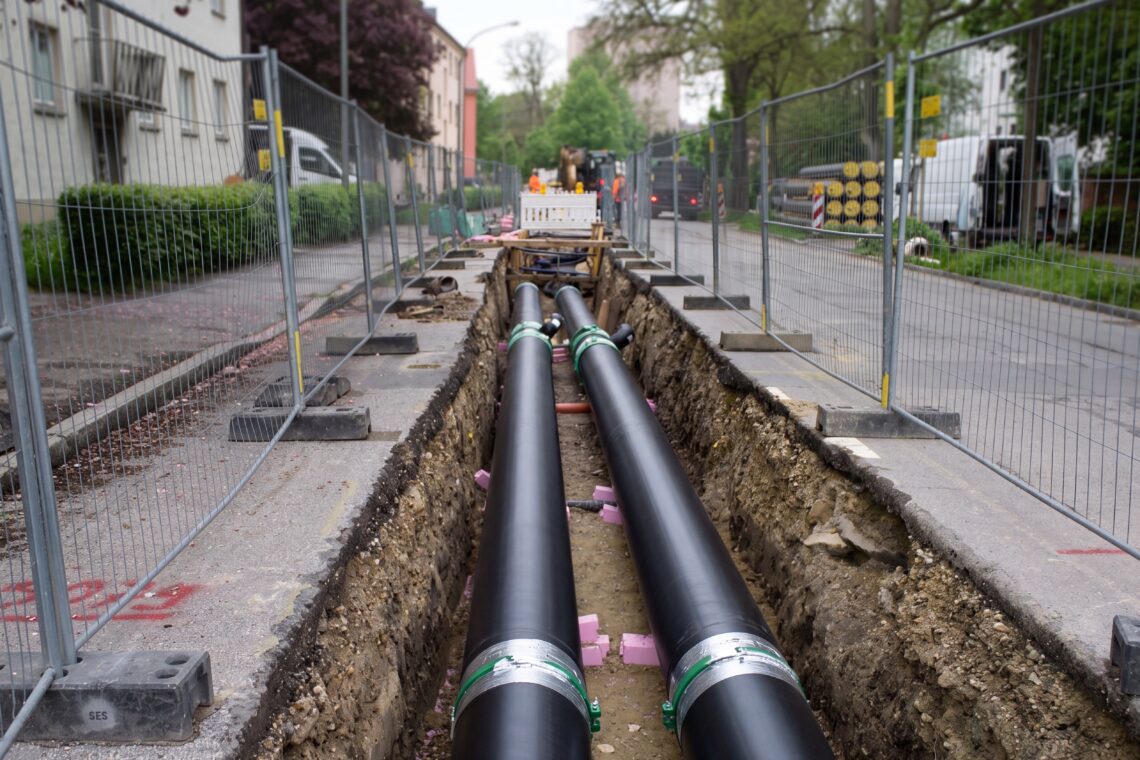
Europe is rewriting how it heats and cools itself, and the rewrite has a number attached. Heating and cooling is roughly half of the EU’s final energy consumption, and, as the European Commission’s heating and cooling overview sets out, it is still about 70% fossil-fuelled — space and water heating alone made up 77.1% of household final energy in 2024, with renewables supplying just 26.7% of heating and cooling. A new EU Heating and Cooling Strategy is due in 2026 to build on the 2016 original, and it does not arrive into a policy vacuum: the binding Energy Efficiency Directive already sets the terms. And underneath every line of that policy sits a piece of hardware it never names — the district heating flow regulator that decides whether each branch actually holds its design flow.
This is an article about one small, unglamorous consequence of all that — what decarbonising a heat network does to the flow inside its pipes — and about that passive flow regulator that keeps the flow where it was set. The policy is the headline. The hydraulics are where an engineer actually works.
Why Europe’s heat networks have to run cooler
District heating is central to the plan, because a network can decarbonise a whole city’s heat at once — swapping a gas boiler house for heat pumps, industrial waste heat, or solar thermal. But the directive does not just ask for cleaner heat; it defines what counts. Under the recast Energy Efficiency Directive (EU) 2023/1791, an “efficient district heating and cooling” system has to climb a glide-path: at least 50% renewables and waste heat by 2035, 75% by 2045, and 100% renewable or waste heat by 2050, while new fossil heat-generation capacity is curtailed.
The catch is that the clean heat sources the directive favours all prefer to work at low temperatures. Heat pumps lose efficiency fast as they are asked for hotter water; industrial waste heat and solar thermal are abundant but lukewarm. So decarbonising a network means running it cooler — the shift to low-temperature, fourth- and fifth-generation district heating. The IEA identifies low-temperature networks as a deployment priority precisely because cooler operation is what lets those sources connect.
And the single most useful number in a low-temperature network is its return temperature. The cooler the water that comes back to the plant, the larger the temperature drop across each building, the less water has to be pumped for the same heat, the smaller the distribution losses, and the higher the efficiency of every heat pump and heat-recovery unit on the system. Return temperature is the lever that European DH operators, and bodies like Euroheat & Power, keep returning to. Lowering it is most of the efficiency prize.
The balance underneath the temperature
Here is the part that policy documents skip. A low return temperature is not a setting you dial in. It is the result of every building on the network drawing its design flow and no more — taking the heat it needs and sending the water back cold. The moment one branch draws too much, it short-circuits: water rushes through faster than the building can cool it, comes back warm, and drags the whole network’s return temperature up. Meanwhile the branches downstream of it are starved, so someone turns up a pump to compensate, and the over-flow gets worse.
The mechanism is plain. Flow through a fixed restriction rises with the differential pressure across it. A heat network’s differential pressure is never still — variable-speed pumps modulate, zones open and close, demand swings across the day and the seasons. So an unregulated branch is a moving target: when system pressure is high, it over-draws; when it sags, it under-delivers. The balance an engineer set at commissioning, with the network at one condition, does not survive the network moving to another.
That is why a heat network’s hydraulic balance is not a state you reach. It is a state you keep losing. Every condition change pulls the distribution off the point it was balanced to, and the cooler the network is asked to run, the less margin there is to absorb the drift before return temperature climbs.
The Recommissioning Trap
We have a name for the cost of that, because it shows up everywhere balancing is done by hand. We call it the Recommissioning Trap: the pattern where a network never finishes balancing, because every condition change re-opens the task. Commission the system, balance the branches, sign it off — and the first seasonal swing, pump replacement, or new connection re-opens the job. Manual balancing creates the trap. The balance is correct only for the conditions it was set in, and a flexing network is never in those conditions for long.
In a low-temperature network the Trap is expensive in a specific way. The whole efficiency case for running cooler rests on a balance that holds across partial load — and partial load is where a manually balanced network drifts furthest from its commissioned state. “We balanced this network when it was built” is not an answer to the return-temperature question when the network has been modulating, expanding, and re-pumping for a decade since. The drift is invisible until someone trends the return temperature and finds it has crept up by degrees nobody authorised.
What a district heating flow regulator does
The fix is mature, passive, and mechanical: a district-heating flow regulator installed in each branch or riser, doing the job of an automatic balancing valve. The regulator holds the flow rate constant regardless of the differential pressure across it. A rubber element deforms against a conical seat in proportion to the pressure: when system pressure rises, the element closes slightly and the flow stays at design; when pressure falls, it opens. There is no actuator, no signal, no controller to tune, and no setting that can drift out of calibration — the regulation is built into the geometry.
On a district-heating or building network the effect maps straight onto the problem above:
- Each branch draws its design flow and no more, whatever the differential pressure is doing, so no consumer over-flows and short-circuits warm water back into the return.
- Because no branch over-draws, the branches downstream are not starved — the network stays balanced across the full flexing load range, not just at the commissioned condition.
- The Recommissioning Trap is closed: the balance is mechanical, so it does not have to be re-done after every seasonal swing, pump change, or new connection.
- The large distribution mains take the Wafer form of the regulator; individual Threaded units sit on branch and riser balancing lines, governing flow without a control system bolted to each one.
A word on where this sits relative to the controls already on a network, because the honest distinction matters. A pressure-independent control valve — a PICV — also holds flow regardless of pressure, but it is an active device: it has an actuator and takes a signal, because its job is to modulate flow to a temperature or BMS demand. A passive flow regulator does not modulate and does not compete with that role. It does one narrower thing: it caps a line at its design flow so the line cannot over-draw, mechanically, with nothing to power or commission. On the many branches that simply need to be held to a fixed design flow, that is the whole job — and doing it passively is what keeps it out of the Recommissioning Trap.
The honest boundary
A district heating flow regulator does not lower a network’s return temperature by itself. It does not generate heat, recover heat, decarbonise the source, or control a temperature, and it does not replace a PICV or a building management system. It has no opinion about how hot the water is.
What it does is remove the hydraulic imbalance that prevents a network from running cool: it stops branches over-flowing and starving each other as pressure moves, so the temperature drop the network was designed around actually survives partial-load operation. Low return temperature is the goal; stable per-branch flow is the precondition. The regulator delivers the precondition and nothing more — which, in a problem where the directive rewards efficiency and the network spends its life away from its design point, is a lever an engineer holds directly.
The proof point
Bertfelt’s flow-control work sits exactly on this line. The mechanism is the same one described in controlling the water flow rate inside a cooling system: holding a fixed, pre-set flow in a circuit regardless of the pressure available, so each part of the loop gets the flow it was designed for and no more. On a heating network that is the definition of balance — and holding it with a passive BT-Maric flow regulator means the balance is set once and kept by the geometry, not re-chased every time the network changes duty.
The application has always been described in terms of stable, accurate flow. The EU’s decarbonisation push simply raises the stakes on the same mechanism. A network that ran hot could tolerate a balance that was roughly right. A network being asked to run as cool as the directive now expects cannot — and the device that keeps each branch to design, through every swing, is the same passive regulator that was already holding the line.
Frequently asked questions about the district heating flow regulator
How does a passive district heating flow regulator help a network run at a lower return temperature?
Indirectly but decisively. Low return temperature depends on every building drawing its design flow and sending the water back cold. An over-flowing branch short-circuits warm water into the return and raises the network’s return temperature. A flow regulator caps each branch at its design flow regardless of pressure, so no branch over-flows — which removes one of the main hydraulic causes of a creeping return temperature. The regulator does not set the temperature; it protects the flow condition that lets the temperature stay low.
Where in the network does the regulator install?
In each branch or riser whose flow you want fixed, between the variable distribution pressure and the consumer it serves. Threaded units suit individual branch and riser balancing lines; the larger Wafer form governs flow in distribution mains. The objective is to place the regulator so the flow downstream of it is held at design regardless of what the differential pressure upstream is doing.
Isn’t this just a PICV?
No — and it is not meant to replace one. A PICV is an active, actuated valve that modulates flow to a control signal. A passive flow regulator has no actuator and no signal; it simply holds a line to its pre-set design flow mechanically. On branches that need modulating control, a PICV is the right tool. On the many branches that just need to be held to a fixed design flow and kept out of the rebalancing loop, a passive regulator does that one job without anything to power, signal, or re-commission.
Does it need power, controls, or recommissioning?
No. The valve is passive and self-contained — no power, no signal, no control integration. It is specified for the design flow and installed in the line; the regulation happens mechanically as pressure varies. Because the balance is built into the geometry rather than set by hand, it does not have to be re-established after seasonal swings, pump changes, or new connections — which is precisely how it exits the Recommissioning Trap.
What pressure range does it work across?
The rubber element needs a minimum differential — roughly 1.4 bar on the standard compound — to deform into its regulating position; below that it passes flow without regulating, so the mechanism is paused, not failed. The standard compound regulates up to 10 bar, with alternate compounds extending the range to 20 bar. Body materials and control-rubber compounds are selected for the temperatures and water chemistry of heating service.
Does this apply to heating, cooling, or both?
Both. The same logic holds wherever a network of parallel branches shares one variable pressure — district heating, district cooling, and the hydronic circuits inside a building. Anywhere balance has to survive partial-load operation, decoupling each branch’s flow from the system pressure is the lever.
Europe’s heat is going to keep decarbonising, and decarbonising means running cooler — the 2026 Heating and Cooling Strategy and the Energy Efficiency Directive make that the direction of travel, not a choice. No flow regulator will decarbonise a heat source or pull a single degree out of a return line on its own, and it should not be sold as if it could. What it does is narrower and real: it keeps each branch to its design flow while the network flexes underneath it, so the balance the whole low-temperature case depends on does not have to be re-commissioned every season. BT-Maric flow regulators — Threaded for branch and riser lines, Wafer for distribution mains — are the passive device that holds that balance. The cooler Europe asks its networks to run, the more the balance nobody finishes is the one most worth building to hold.
Contact our experts!
Our team of experts is here to provide you with the knowledge and support you need. Whether you have questions about our products, need assistance choosing the right solutions, or want to discuss your unique requirements, our specialists are ready to help. With years of experience and a deep understanding of industry standards, we’re committed to offering you reliable guidance every step of the way. Don’t hesitate to get in touch – we look forward to assisting you!