
 Nederlands
 Français
 Deutsch
 Svenska
 Español



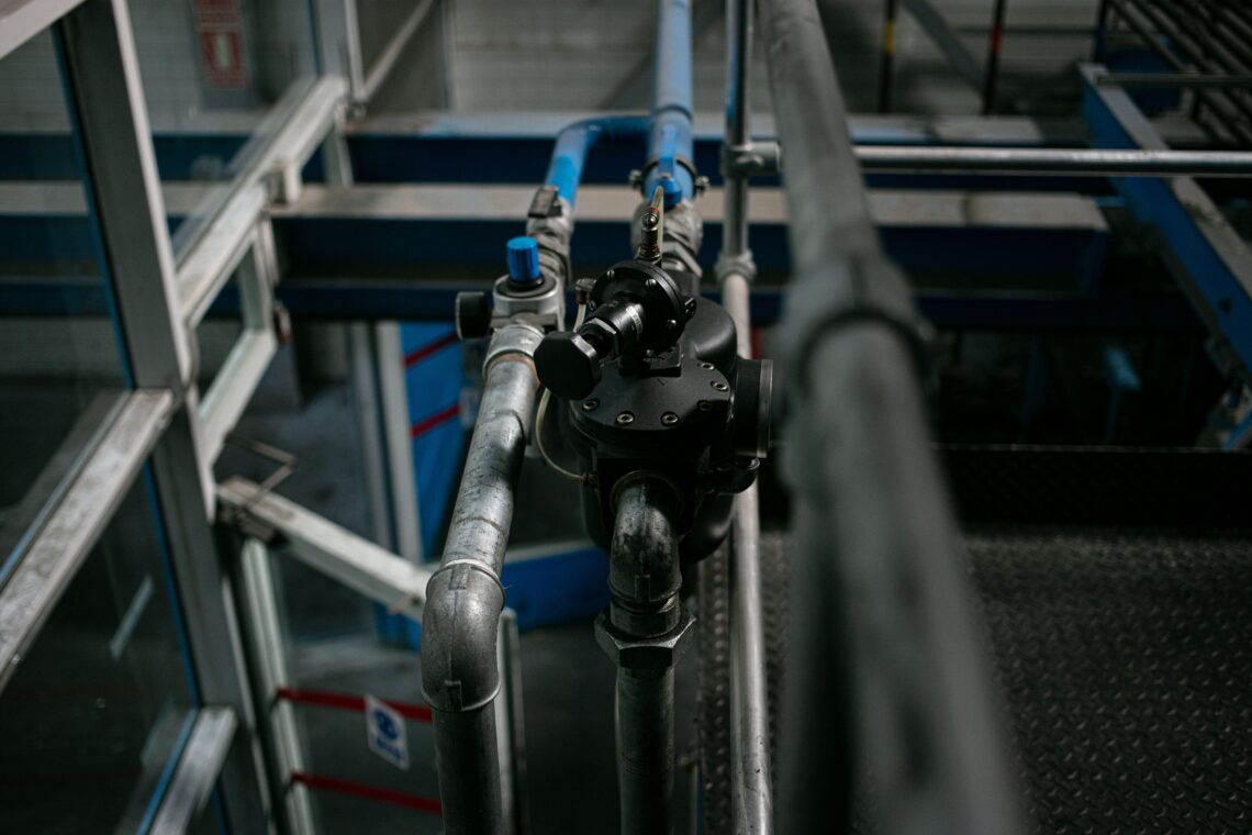
From 23 to 27 August the water sector gathers in Stockholm for World Water Week, under the theme Water for People and Progress. Hundreds of sessions will cover governance, financing, treatment, reuse and allocation. Almost none will cover the last meter of pipe — which is where industrial water conservation is actually decided, one outlet at a time.
That is not a criticism of the programme. Those are the right subjects. But they share an assumption worth naming: that the task is to find, clean, move and allocate water better. The cheapest cubic meter is the one that never leaves the pipe.
Where the water actually goes
The headline split has been stable for years. UNESCO’s 2024 World Water Development Report puts agriculture at roughly 70% of global freshwater withdrawals, industry at just under 20%, and municipal use at about 12%.
Industry, which accounts for nearly one-fifth of global freshwater withdrawals, is the sector with the shortest decision chain. A farm’s water use is bound up with weather, soil and crop choice. A factory’s is bound up with equipment, and equipment can be changed on a maintenance window.
The efficiency trend is real but slow. UN reporting on SDG target 6.4 shows water-use efficiency rising from $17.4 per cubic meter in 2015 to $20.8 in 2021 — a 19% improvement, with the industrial sector improving by 15% over the same period.
Those numbers describe value created per cubic meter. They do not tell you whether the cubic meters being drawn were the ones the process actually needed — and that question is where industrial water conservation either becomes measurable or stays rhetorical.
The liter nobody decided to use
Every water-using process is specified as a rate. A wash step needs so many liters per minute. A cooling circuit needs so many. A dosing line needs so many. Those numbers are chosen by engineers and written into the design.
What arrives at the outlet is a different quantity, because a fixed opening does not deliver a rate — it delivers whatever the pressure behind it allows.
- Mains pressure rises overnight, when demand across the network falls, and every open outlet draws harder for the same setting.
- Branches near the pump or low in the building sit at higher pressure than the ones the balance was set for, and over-draw permanently.
Neither shows up as a fault. The wash still washes, the circuit still cools, the line still doses. There is no alarm for using more water than the specification called for, because nothing has failed. The meter simply reads higher, and the surplus is filed under consumption.
This is why industrial water conservation programmes so often stall after the obvious wins. The remaining volume is not being wasted by anybody’s decision; it is being drawn by physics, at outlets that are behaving exactly as a fixed opening behaves.
Pressure-Coupled vs. Pressure-Decoupled Flow
This is the distinction that decides whether a water target is achievable at all.
Pressure-coupled flow is what a fixed opening delivers: a rate that rises and falls with the pressure across it, roughly with the square root of that pressure. Set it correctly on commissioning day and it is correct on commissioning day.
Pressure-decoupled flow is a rate held at its design value across a working band of pressures, without adjustment, sensors or power. The outlet passes what the process specified, and surplus pressure changes nothing.
A plant built entirely from pressure-coupled outlets cannot hold a water figure, because the figure was never under its control — the network’s pressure was. Every hour spent at above-design pressure is collected as the Over-Circulation Penalty: water moved, and pumping energy spent, for no delivered duty.
What a flow regulator does
A flow regulator is a self-adjusting restriction. Inside it, a flexible rubber element deforms against a conical seat in proportion to the pressure differential across the valve, narrowing the opening as pressure rises and opening it as pressure falls.
The delivered rate stays at its pre-set value, within the tolerance of the control rubber fitted. When network pressure climbs overnight, the element narrows and the outlet still passes its design flow. When pressure sags at the far end of the plant, the element opens and the outlet still passes its design flow.
The mechanism explainer shows the element and seat in section.
It works within a window, and the window belongs to the control rubber rather than to the valve. Each compound has its own minimum differential; below it the element cannot deform into its regulating position, so it passes flow without regulating — paused, not broken.
- Precision (standard) — 1.4 to 10 bar, and the only compound rated to ±10% of nominal.
- Low Pressure — 0.45 to 5 bar, for sites whose differential never reaches the standard floor.
- HP1 / EPDM — 1.4 to 15 bar.
- HP2 / EPDM-HP2 — 1.7 to 20 bar; the widest range, but note the higher floor, not the standard one.
Every compound other than Precision holds ±20% of nominal. That band is the honest bound on the whole argument: capping converts a specified rate into a delivered one within a stated tolerance, not into a single exact number. The typical performance data gives the windows by size and compound.
Being passive is the point for a water programme:
- No power supply to run, and no actuator to fail.
- No signal to integrate into a control system.
- No calibration to schedule, and nothing to drift out of tune between maintenance visits.
What it does not do
It is worth being equally plain about the boundary, because water strategy is full of things that sound similar and are not.
- It does not treat water, or make a lower-grade source usable.
- It does not recycle or reclaim anything; a liter it caps is a liter not drawn, not a liter recovered.
- It does not meter or report — you will not see the saving on a dashboard unless something else measures it.
- It does not find or fix leaks in the distribution network upstream of it.
- It is not field-adjustable; the rate is set at the factory, so a changed process duty means a different unit rather than a new setting.
It caps draw at the design rate. That is the whole function, and in a plant whose outlets are all pressure-coupled, it is the missing one.
Where it saves most
Surplus pressure is not evenly distributed, so neither is the opportunity for industrial water conservation. The placement follows the geometry.
- Wafer — DN 20 to DN 300, up to 8,854 L/min. Sits between flanges at the plant inlet or on a main, capping the incoming supply with one device: the natural place when the mains is over-pressured relative to the process. It bounds the group’s aggregate draw, not each outlet’s individual rate.
- Threaded — 1/8″ to 2″, 0.15 to 342 L/min. Sits in an individual branch, wash station or dosing line, holding one duty to its design rate regardless of what its neighbours are doing. This is the form that makes a single outlet’s figure true.
- Insert — up to 233 L/min. Fits where space is tight, dropping the regulating element into an existing fitting rather than requiring new pipework.
The rule is the same in each case: put the regulator between the variable pressure of the supply and the outlet whose rate you want held. The how-to-specify guide works through sizing.
Frequently asked questions
How does a flow regulator support industrial water conservation if it saves nothing by itself?
It removes the gap between the rate a process was specified for and the rate it actually draws. That gap is invisible because it never causes a failure, and it grows with every hour the network runs above design pressure.
Capping each outlet converts a specified figure into a delivered one, within the ±10% or ±20% band of the control rubber fitted. That is what makes a water target auditable rather than aspirational.
Isn’t a pressure-reducing valve the same idea?
No, and the difference matters. A pressure-reducing valve holds a downstream pressure; the flow through the outlets behind it still varies with their own resistances and duty cycles. A flow regulator holds a rate. Pressure control is useful upstream — it is not a substitute for capping the individual draws.
What about a manual balancing valve or a fixed orifice?
Both are correct at exactly one pressure difference: the one present when they were set. When network pressure changes, the flow through them changes too, because they are still fixed openings.
A flow regulator is correct across its whole window without being re-set, and stays correct as the plant ages and outlets are added. The exception is a change to the duty itself: the rate is factory-set rather than adjustable in the field.
Does it need power, sensors, or a controller?
No. It is passive and self-contained — no electricity, no signal, no control integration. It is specified for the design flow and installed in the line, and regulation happens mechanically as pressure varies. That makes it a retrofit rather than a re-design of the plant.
Where should a plant start?
Where surplus pressure is largest and most persistent:
- The incoming main — the whole site’s draw sits behind it, and mains pressure is the least controlled variable on the plant.
- Wash-down and cleaning stations — high duty cycles, open outlets, and rates nobody re-checks after commissioning.
- Once-through cooling — continuous draw, so every hour above design pressure accumulates.
- Branches low in the building or close to the pump — permanently above the pressure the balance was set for.
Those are the outlets whose draw is furthest from the specification, and therefore where capping to design removes the most water.
The sessions in Stockholm this week are about the right things. Water is a governance problem, a financing problem and an allocation problem, and it will not be solved at the outlet alone.
But every plan agreed there eventually arrives at a pipe with an opening in it, and that opening will deliver whatever the pressure behind it allows unless something decides otherwise.
A passive flow regulator — Wafer on the main, Threaded on the branch, Insert where space is tight — is how a specified rate becomes the delivered one. It is unglamorous, it reports nothing, and it is the part of industrial water conservation that no summit will announce.
Contact our experts!
Our team of experts is here to provide you with the knowledge and support you need. Whether you have questions about our products, need assistance choosing the right solutions, or want to discuss your unique requirements, our specialists are ready to help. With years of experience and a deep understanding of industry standards, we’re committed to offering you reliable guidance every step of the way. Don’t hesitate to get in touch – we look forward to assisting you!