
 Nederlands
 Français
 Deutsch
 Svenska
 Español



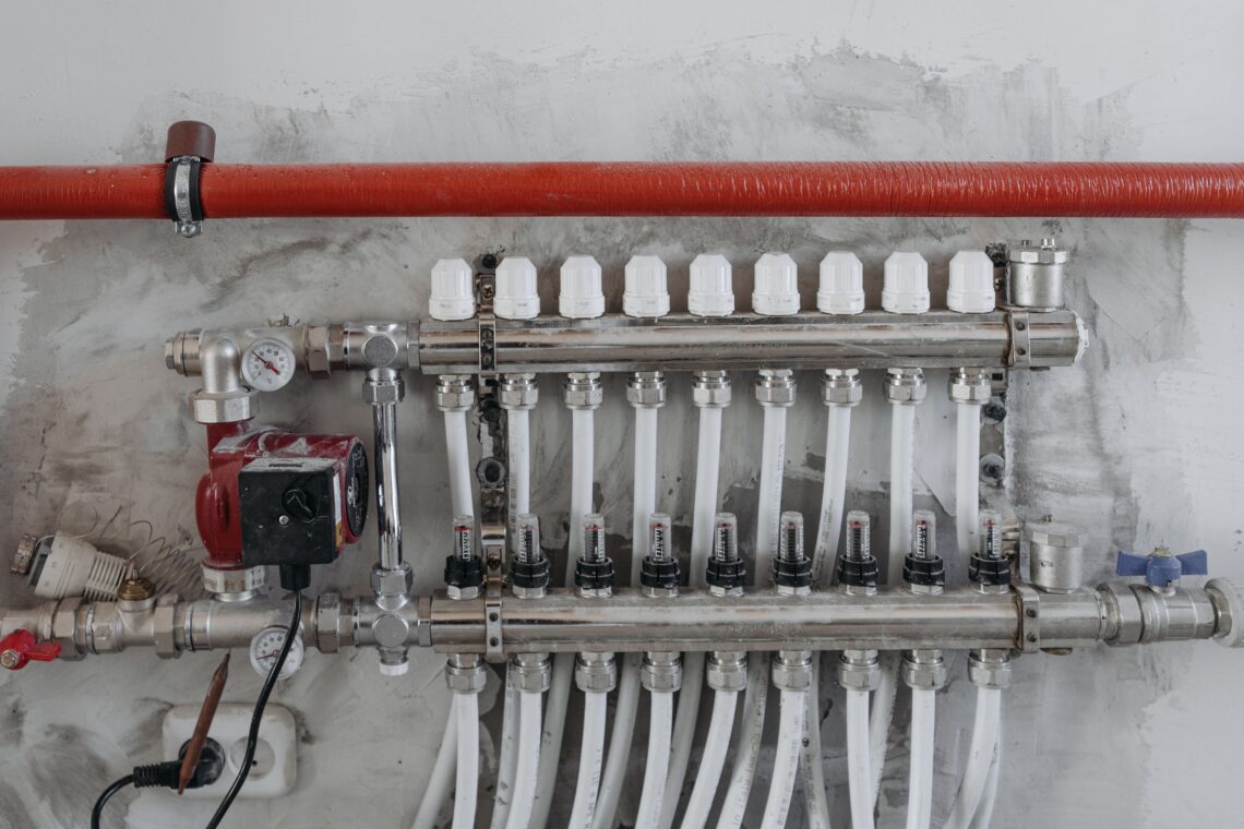
Flow through a fixed restriction is not a fixed quantity. Open the supply harder and an orifice, a length of small-bore pipe, or a hand-set valve passes more; let the supply sag and it passes less. The rate rises and falls with the pressure across the restriction — roughly with the square root of it — and nothing about a fixed opening holds it to a target. Correcting that is the entire job of a constant flow valve.
This is the first fact of flow control, and almost every avoidable cost in a piped system can be traced back to it. When flow follows pressure, and the pressure is rarely the design pressure, the system spends most of its life delivering the wrong rate.
The direction of that error is not random. It is almost always too much. Understanding why is the difference between paying an invisible bill forever and specifying it away once.
Systems are designed for one condition and run in many
Every distribution system is sized for a worst case: the hottest day, the fullest occupancy, the longest run with the most fittings, the dirtiest filter. The pump is then chosen to beat that worst case with margin to spare, because an undersized pump is a failed installation and an oversized one merely looks safe.
So the machine at the heart of the system is, by deliberate design, capable of more head and more flow than the system needs on almost any real day.
That margin does not sit idle. It shows up as surplus pressure at every outlet, coil, and branch — and because flow follows pressure, surplus pressure becomes surplus flow. The worst case the system was sized for arrives rarely; the part-load condition, where loads have dropped and valves have opened wide, is the normal state.
- The branch near the pump — sits at high pressure and over-draws.
- The parallel branch with less pipe and fewer fittings — sits at lower resistance and over-draws harder still.
The system was balanced on paper for one operating point, and it is running at a different one — as it will for most of its service life. The result is a system that circulates more water than the job requires, quietly, continuously, and without any alarm to announce it. That surplus has a name.
The Over-Circulation Penalty
The Over-Circulation Penalty is the invisible energy cost of flow that exceeds the design rate. Pumps work harder, energy is spent, and no benefit accrues — the system is paying to move water that does nothing once it arrives.
The penalty is rarely measured because it never appears as a failure. There is no trip, no callout, no flooded plant room. There is only a pump drawing a little more power than it should, every hour of every day, on a bill nobody reads line by line.
At the scale of a single building the penalty is easy to dismiss. At the scale of the grid it is not. The IEA’s analysis of electric motor-driven systems puts motor systems — the pumps, fans, and compressors that move fluids and air — at around 53% of the world’s electricity consumption, and it estimates that roughly a quarter of that could be saved cost-effectively with measures already available.
A meaningful share of that waste is fluid moved for no reason: over-circulation, repeated across millions of systems that all followed the same sound engineering instinct to size for the worst case.
The physics of the penalty is simple. A pump does work on every litre it moves, and moving more litres than the design requires spends more shaft power for no delivered duty.
On a constant-speed pump the surplus is worse than linear, because over-flow pushes the operating point out along the pump curve toward runout, where efficiency falls away and each additional litre costs more than the last. The system is not just spending extra energy; it is spending it at a declining rate of return.
Why the penalty is disproportionate — and cheap to remove
The same steepness that makes over-flow expensive makes correcting it unusually rewarding. Bring the flow in a circuit back down toward its design rate and the pump power needed to move it falls with roughly the cube of the flow reduction: a circuit trimmed to 80% of an over-flowing rate does not need 80% of the power, but closer to half.
This is why capping over-circulation is one of the cheapest efficiency levers in the building — the saving is geometric, not proportional, and it requires no new plant.
The standards bodies have reached the same conclusion. ASHRAE Standard 90.1 requires that hydronic systems be proportionally balanced and that the pump’s surplus head — its “over-heading” — be taken out rather than left to drive uncontrolled flow.
The instinct to remove over-circulation is not a vendor’s opinion; it is written into the energy code. The open question is only how it is removed, and at what point in the system.
The second cost: over-flow degrades the plant, not just the pump
There is a second penalty stacked on the first, and it lands on the equipment the flow is supposed to serve. Heat is exchanged across a coil or a plate by the temperature difference between the water and the load, and that difference is what the chiller or boiler is designed around.
Push more water through a coil than the design flow and it spends less time in contact, picks up or sheds less heat per litre, and returns closer to the temperature it left at. The temperature difference collapses.
To the central plant this “low delta-T” looks like a demand it cannot satisfy efficiently: the chiller runs colder or the boiler runs hotter than it should to make up for water that is barely working, sliding off its own efficient operating point.
So the surplus flow does not merely cost pump energy — it makes the chiller and boiler less efficient at the same time. Over-circulation is a fault that gets more expensive the further downstream you follow it.
The cure at the mechanism: a variable orifice
If the problem is a fixed opening whose flow follows pressure, the solution is an opening that changes to hold flow steady as pressure varies. That is precisely what a constant flow valve is.
Inside it, a flexible rubber element deforms against a conical seat in proportion to the pressure differential across the valve, closing the flow path slightly as pressure rises and opening it as pressure falls, so the delivered rate stays at its pre-set value.
When surplus pressure appears, the element narrows and the path still passes its design flow. When pressure sags at the far end of the system, the element opens and the path still passes its design flow.
The valve is a self-adjusting restriction that targets a rate rather than an opening — the mechanism explainer shows the element and seat in section.
This is the mechanical inverse of the penalty. Where over-circulation is flow that follows pressure, a constant flow valve is flow that ignores it — within a working window. The element needs a minimum pressure differential to deform into its regulating position; below that it simply passes flow without regulating, so the mechanism is paused, not broken.
Above it, the valve holds its rate across a wide band — on the standard control rubber from roughly 1.4 bar up to about 10 bar of differential, with a low-pressure compound regulating from a smaller differential and alternate compounds extending the range to 20 bar. The typical performance data gives the windows by size and compound.
It is worth being precise about what this is not. A manual balancing valve is a fixed orifice set by hand: it is correct at exactly one pressure difference — the one present on the day it was commissioned — and wrong at every other, which is most of the time.
A constant flow valve is correct across its whole window without adjustment, and stays correct as loads vary, as the system ages, and as branches are added. It does not need re-balancing because it was never balanced to a single condition in the first place.
Doesn’t capping the flow just waste the surplus as pressure drop?
This is the objection every engineer should raise, and the answer is the point of the whole principle. Capping flow does not burn the surplus energy — it prevents the surplus from being spent at all.
A throttle that holds a fixed flow while dropping pressure would indeed be wasteful, converting head into nothing. But a constant flow valve does not hold the flow high and dissipate the difference; it reduces the flow to the design rate. Less flow moves the pump’s operating point back down its own curve, and the shaft power the pump draws falls with it.
The energy that was being spent on over-circulation is not redirected — it is never demanded from the motor. That is why the device sits on the demand side of the Over-Circulation Penalty rather than the supply side: it changes what the system asks the pump for, and the pump answers with less power.
Where the valve goes
The principle is the same everywhere, but the placement follows the geometry.
- Wafer — sits at a pump discharge or on a main, governing the flow into a whole group of branches with one device: the natural place to cap a system that is over-heading globally.
- Threaded — sits in an individual branch or riser, holding one circuit to its design rate regardless of what its neighbours do.
- Insert — fits where space is tight, dropping the regulating element into an existing fitting.
In each case the rule is the same: put the valve between the variable pressure of the supply and the outlet whose flow you want held constant. The how-to-specify guide works through sizing for each.
Frequently asked questions
What is the difference between a constant flow valve and a balancing valve?
A balancing valve is a fixed restriction set by hand to give the right flow at one pressure difference. When the pressure difference changes — a load drops, another branch closes, the pump runs at part speed — the flow through it changes too, because it is still a fixed orifice.
A constant flow valve holds the flow to its pre-set rate across a whole range of pressure differences, adjusting its own opening mechanically. One is correct at a single operating point; the other is correct across the operating range.
Doesn’t a variable-speed pump already solve over-circulation?
A variable-speed drive is valuable and complementary, but it acts globally — it lowers the head the whole system sees. It cannot make two parallel branches with different resistances draw their correct individual flows; the branch with less pipe still over-draws relative to its neighbour.
Speed control sets how hard the pump pushes; constant flow valves set how the resulting flow is shared. Systems that use both get the global saving of the drive and the per-branch correctness of the valves.
What pressure differential does the valve need to work?
It needs a minimum differential to deform the rubber element into its regulating position — roughly 1.4 bar on the standard compound, and less on the low-pressure compound. Below that minimum it passes flow without regulating; the mechanism is paused, not failed.
The standard compound regulates up to about 10 bar of differential, and alternate compounds extend the range to 20 bar. The regulating window is selected for the application when the valve is specified.
Does it need power, sensors, or a controller?
No. A constant flow valve is passive and self-contained — no electricity, no signal, no control integration. It is specified for the design flow and installed in the line; regulation happens mechanically as pressure varies. That makes it a retrofit onto existing systems rather than a re-design of the plant.
Where does it save the most?
Wherever surplus pressure is largest and most persistent: near the pump, on downhill or short-run branches, and in any system whose pump was sized for a worst case that rarely arrives. Those are exactly the places a pressure-coupled outlet over-draws hardest — and therefore where capping flow to design removes the most over-circulation.
Almost every piped system carries the Over-Circulation Penalty, because almost every one is built the right way: sized for a worst case, driven by a pump with margin, and left to run at conditions milder than the one it was balanced for. The penalty is not a design mistake to be ashamed of; it is the predictable consequence of flow following pressure. What is optional is whether you keep paying it.
A passive constant flow valve — Wafer on the main, Threaded on the branch, Insert where space is tight — caps each path at the rate it was specified for, so the pump is never asked to over-circulate in the first place. The physics that creates the penalty is the same physics that removes it: decouple the flow from the pressure, and the surplus simply stops being spent.
Contact our experts!
Our team of experts is here to provide you with the knowledge and support you need. Whether you have questions about our products, need assistance choosing the right solutions, or want to discuss your unique requirements, our specialists are ready to help. With years of experience and a deep understanding of industry standards, we’re committed to offering you reliable guidance every step of the way. Don’t hesitate to get in touch – we look forward to assisting you!