
 Nederlands
 Français
 Deutsch
 Svenska
 Español
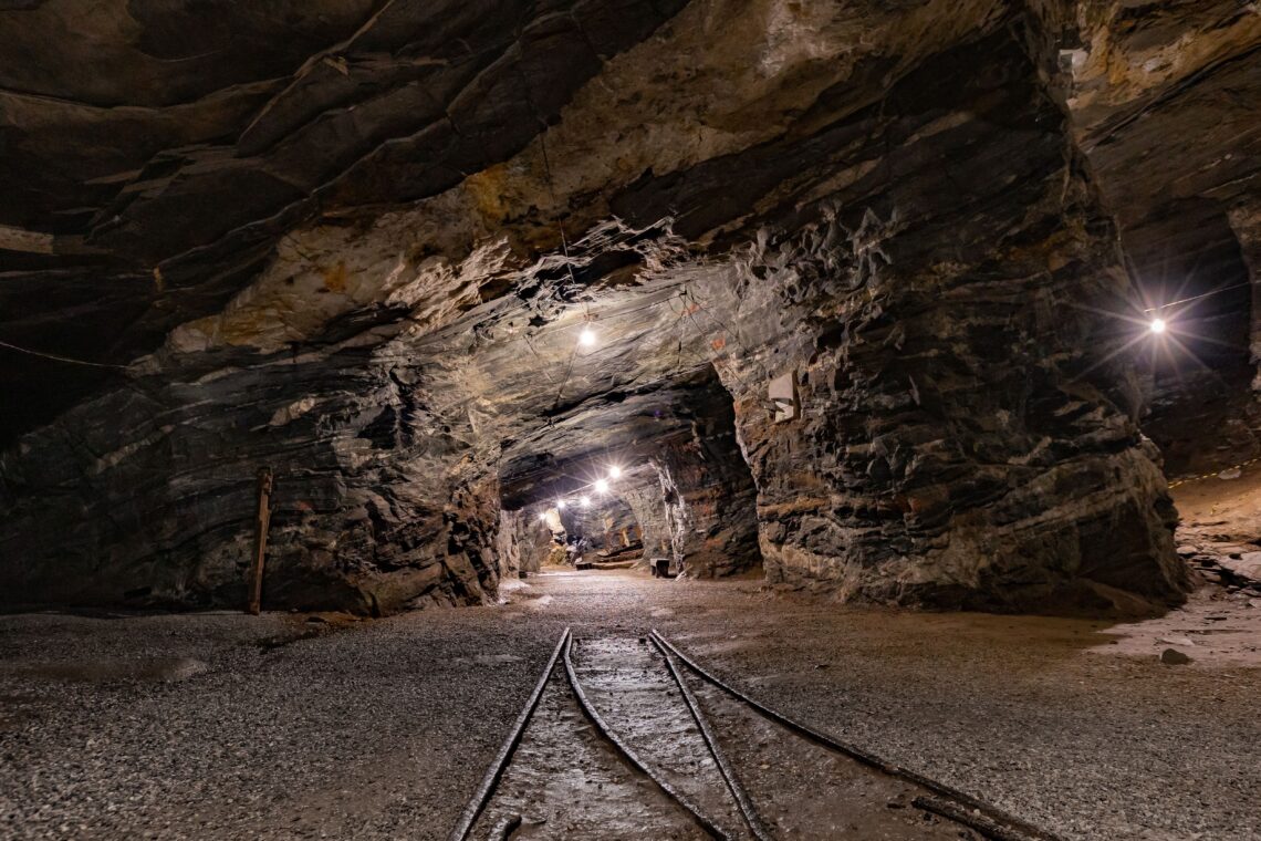
The fastest-growing demand on the planet’s mineral reserves is now being set in data centres. Every tier of the AI and clean-energy build-out — batteries, motors, grid copper, rare-earth magnets — terminates in a mine, and the mines are being asked to deliver more, faster, than at any time in modern history. The IEA’s Global Critical Minerals Outlook 2025 projects lithium demand growing roughly fivefold by 2040, with announced supply still falling short of projected copper and lithium demand. The catch is where that supply has to come from. In April 2026, The Conversation described the human cost of the rush in stark terms: the race to mine critical minerals for AI and clean energy is creating “sacrifice zones” — and water sits at the centre of the harm.
This is an article about that water, and about an unglamorous fact buried inside it: a surprisingly large share of a mine’s freshwater draw is not extraction, processing, or tailings. It is water circulated through equipment beyond what the equipment needs — and that part is demand, which is where engineers actually work.
Where the water goes
Mining’s freshwater footprint is small as a share of national totals and enormous wherever a mine happens to sit. The U.S. Geological Survey’s mining water-use data shows groundwater supplying the majority of mining withdrawals — so the draw lands directly on the aquifers a region depends on. And the geography is unforgiving: the ICMM’s water-stewardship work notes that a significant fraction of critical-mineral mines and deposits sit in areas already under high or extremely high water stress. The same Conversation analysis records that in Chile’s Salar de Atacama, mining accounts for up to 65% of regional water use, and that 2024 global lithium production alone required an estimated 456 billion litres of water.
Against numbers like those, a few cubic metres per hour at a pump gland sounds like a rounding error. It is not, and the reason is that there are thousands of them, running continuously, for the life of the mine.
The flow nobody meters
To move ore, a mine runs slurry pumps — hundreds of them on a large site. Each centrifugal slurry pump has to keep abrasive solids away from its shaft seal, and the standard method is gland water: clean water pumped continuously into the gland packing or mechanical seal at a pressure slightly above the pump’s, so slurry cannot back-flow into the seal. The water lubricates the shaft sleeve, cools the seal, and flushes fines away. It is essential, and it never stops while the pump runs.
It is also remarkably thirsty. As Oil Sands Magazine’s primer on gland seal water sets out, normal gland-water flow for a slurry pump runs from around 5 m³/hr to as much as 25 m³/hr once packing is worn — and a single small slurry pump on a traditional sealing arrangement can consume close to eight million litres of water a year on gland service alone. Multiply that by the pump count on a working mine and gland water becomes one of the largest continuous freshwater flows on site. It is also one of the least watched: it is plumbed in, set roughly, and forgotten, because the pump keeps running either way.
Any water engineer recognises the pattern, because it is the same one that governs every distribution network: a finite supply, many consumers, and a balance that holds only as long as each consumer draws inside the envelope its job requires.
The Over-Circulation Penalty
Here is the uncomfortable arithmetic of an unregulated gland line. Flow through a fixed restriction rises with the pressure across it. Gland water is fed from a shared supply whose pressure varies with pump duty, header demand, and how many other glands are drawing at that moment. When supply pressure is high, every unregulated gland pulls more than the flow its seal actually needs. The seal that wanted twelve litres a minute takes twenty. Nobody notices, because the seal is still flushed and the pump still turns. The excess is invisible — until you run a mass balance against the borehole feeding it.
We call this the Over-Circulation Penalty: the cumulative cost of every gland drawing more water than its seal requires, simply because nothing on the line holds the flow to its design value. Per gland it is a small overshoot. Across a pump hall — and then across a site drawing from a stressed aquifer — it becomes the dominant avoidable withdrawal in the gland-water system.
The penalty compounds in both directions. Upstream, the borehole and gland-water pumps work harder than the design assumed, drawing the source down faster and burning pumping energy for water nobody needed. Downstream, the over-supplied gland gains nothing useful — excess gland water dilutes the slurry or the product, which then has to be thickened or evaporated back out, spending still more energy to undo the over-supply. The water is extracted, paid for twice, and wasted at both ends.
The Drift Tax
There is a second, slower mechanism, and gland systems are especially prone to it. Gland-water demand is not constant over a pump’s life. As packing wears, the clearance opens and an unregulated line passes progressively more water — the same physics that takes a worn pump’s gland flow from 5 toward 25 m³/hr. Add the rest of the normal churn of a working plant — pumps swapped, headers re-pressurised, lines re-plumbed — and the flow distribution wanders steadily off whatever point it was set to at start-up.
We call the accumulated cost of that slow wandering the Drift Tax: the price a system pays for the gap between the balanced state someone set at commissioning and the unbalanced state it has drifted into since. On gland water the Drift Tax is rarely audited, because the symptom — slightly more water through a worn seal — looks like normal wear, not like an unauthorised withdrawal. In a water-stressed catchment, that distinction matters. “We set the gland flows when the plant was built” is not an answer to the over-extraction question when the plant has been running, and wearing, for a decade since.
What deliberate management looks like at the gland
The fix is mature, and it is mechanical. It looks like a passive constant flow valve installed in each gland-water line. The valve holds the flow rate constant regardless of upstream pressure: a rubber element deforms against a conical seat in proportion to the pressure across it, opening or closing the flow path to maintain the pre-set rate. When supply pressure rises, the element closes slightly and the flow stays at design. When pressure falls, it opens. No electronics, no actuator, no setting that can drift — the regulation is built into the geometry.
On a mine’s gland-water system the effect is direct, and it maps onto exactly the demand-side levers above:
- Each gland draws its design flow and no more, regardless of supply pressure or what neighbouring glands are doing.
- The Over-Circulation Penalty is removed at the gland where it originates, not corrected somewhere downstream after the water is already drawn.
- Because the regulation is mechanical rather than set by hand, it does not drift as packing wears — the Drift Tax is capped at installation.
- In a shared supply header, holding each gland to its design flow guarantees that enough water remains for every other gland even if one seal fails open — reliability and conservation from the same device.
A clear boundary belongs here, because it is the honest one. A constant flow valve does not treat contaminated water, recycle a tailings stream, remediate a “sacrifice zone,” or recharge an aquifer. It does exactly one thing: it stops a system from withdrawing more water than it needs. That is a demand-side intervention, and in a setting where the source is a stressed aquifer and the draw is continuous, removing avoidable withdrawal is among the few levers an engineer holds directly.
The proof point
Bertfelt’s flow-control work in mining sits squarely on this demand side. On centrifugal and slurry-pump glands, on mechanical-seal flush lines, and on shared gland-water headers, BT-Maric constant flow valves hold each line to its specified flow regardless of the pressure available at the supply. The application has always been described in terms of protection and uniformity: every gland gets the steady, known flow that maximises seal and packing life, and sensitive seals are shielded from pressure swings. The critical-mineral water story reframes the same mechanism in a larger ledger. A known, fixed gland flow is also a minimum gland flow. A pump hall that cannot over-draw is a pump hall that cannot over-extract — and on a water-scarce site, that is the difference between a flow nobody meters and a withdrawal held to design.
Frequently asked questions about gland-water flow control
How does a passive constant flow valve actually reduce a mine’s water draw?
By holding each gland to its design flow rate regardless of supply pressure. On an unregulated line, gland flow rises with pressure, so seals routinely take more water than they need whenever the supply header is running high. A constant flow valve caps the draw at the pre-set value, so the water that would have been over-circulated is never withdrawn from the source in the first place.
Where in the gland-water system should the valve install?
In each gland-water line, on the supply side of the gland or seal it serves. Threaded variants suit individual gland lines on a per-pump basis; larger Wafer variants regulate a shared supply header where a single device governs the flow into a bank of pumps. The objective is to place the valve between the variable header pressure and the gland whose flow you want fixed.
Does this require changing the pumps or adding controls?
No. The valve is passive and self-contained — no power, no signal, no control integration. It is specified for the design gland flow and installed in the line; the regulation happens mechanically as pressure varies. That makes it a retrofit on existing gland-water systems rather than a capital re-design of the pump hall.
Won’t a pressure-reducing valve do the same job?
No — they solve different problems. A pressure-reducing valve holds downstream pressure constant; the flow through it still varies with the restriction at the gland and with packing wear. A constant flow valve holds flow constant regardless of the pressure differential across it. When the goal is to stop a gland from drawing more water than its seal needs, flow is the variable to fix, not pressure.
What pressure range does the valve work across?
The rubber element needs a minimum pressure differential — roughly 1.4 bar on the standard compound — to deform into its regulating position; below that it passes flow without regulating, so the mechanism is paused, not failed. The standard compound regulates up to 10 bar, and alternate compounds extend the range to 20 bar for high-pressure supply headers. Body materials and control-rubber compounds are selected for the abrasive, chemically aggressive conditions typical of mine water.
Is this a single-pump measure or a site-scale one?
Both, and the link between them is additive. One regulated gland removes one seal’s over-draw. The site-scale effect is the sum of those removals across every gland on every pump drawing from the same stressed source. On a site where, per the USGS mining water-use record, most of that water comes from groundwater, the additive demand-side saving is the fraction of withdrawal that good engineering can actually retire.
The critical-mineral rush is not going to slow, and no constant flow valve will resolve the water conflicts at the mining frontier on its own. But the data is clear that mining’s water harm is concentrated where water is scarcest, and that a meaningful share of a mine’s continuous draw is avoidable over-supply rather than necessary process water. On the demand side, the most direct deliberate management an engineer can specify is the one that stops a system from withdrawing more than it needs. BT-Maric constant flow valves — Threaded for individual gland lines, Wafer for shared supply headers — are that mechanism. The aquifer behind a critical-mineral “sacrifice zone” is the silent casualty. Holding every gland to its design flow is the quiet, unglamorous intervention on the side of the ledger a mine can actually reach.
Contact our experts!
Our team of experts is here to provide you with the knowledge and support you need. Whether you have questions about our products, need assistance choosing the right solutions, or want to discuss your unique requirements, our specialists are ready to help. With years of experience and a deep understanding of industry standards, we’re committed to offering you reliable guidance every step of the way. Don’t hesitate to get in touch – we look forward to assisting you!